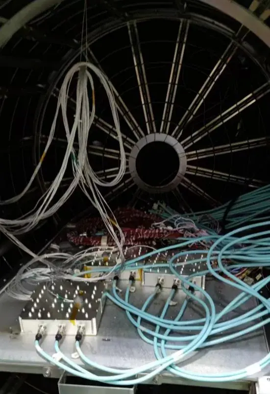
Our product range is organised around two things we build ourselves: RF components and the antenna feed sub-systems they go into. The core devices are passive filters, transceiver modules, phase shifters and antennas, covering antenna feed systems, antenna-embedded components and radar front-ends.
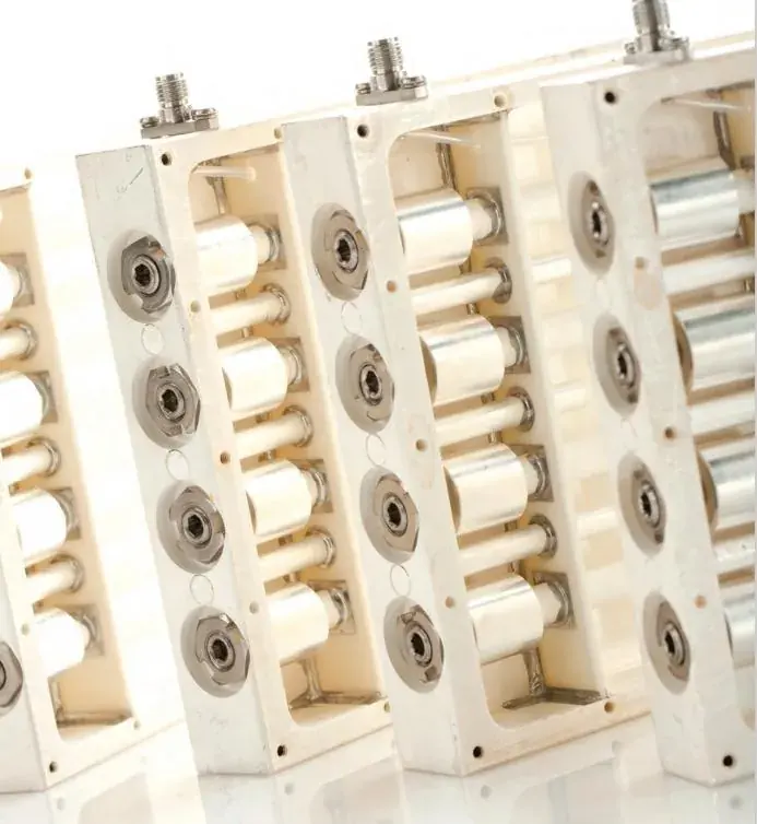
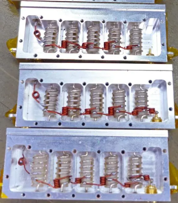
Filters are where the range begins. High-power applications use cavity filters; where space and weight are constrained we offer miniaturized cavity, dielectric-loaded and waveguide topologies; system-level requirements are delivered as combiners and duplexers, specified item by item on isolation, power handling and temperature range.
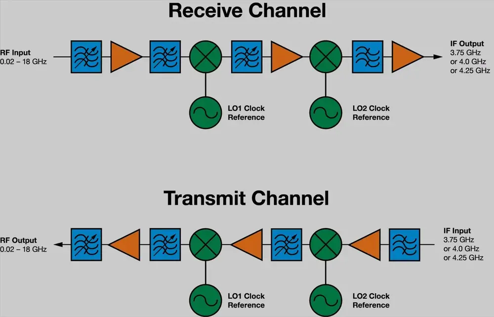
Transceiver modules integrate the duplexer, power amplifier and low-noise amplifier into a single housing and are delivered directly as a radar front-end. Antennas and phase shifters serve satcom phased arrays, airborne and vehicle platforms, navigation, and beam steering in phased array radar.
The tables below show what each line has actually delivered in production programmes. Frequency, power and rejection for a new project are engineered to the application — the ranges shown are not an upper limit.
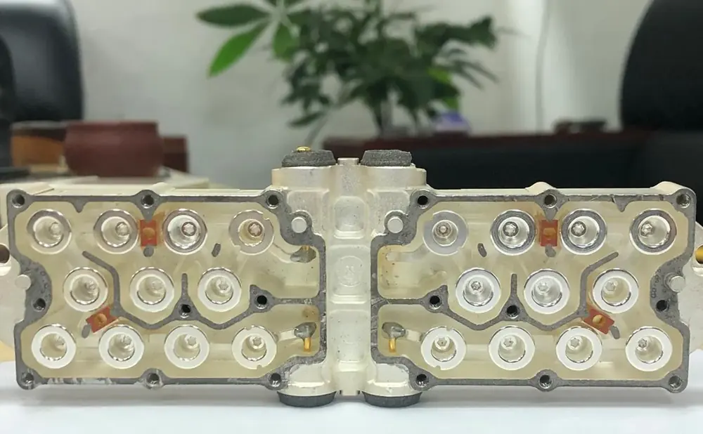
Passive filters are the starting point of the whole range. High-power applications take the metal cavity route; system-level requirements become combiners and duplexers. Six topology families are available — lumped element, metal cavity, dielectric-loaded, tubular, air stripline and waveguide. Which one is used is decided by the system constraints, not by habit.
The inherent difficulty is that the specifications constrain each other. Reducing insertion loss usually means increasing volume; raising rejection costs group-delay flatness; increasing power handling means reworking connectors and cavity structure. Every model is therefore a compromise under a defined set of constraints, confirmed item by item in simulation.
| Topologies | Lumped element · metal cavity · dielectric-loaded · tubular · air stripline · waveguide |
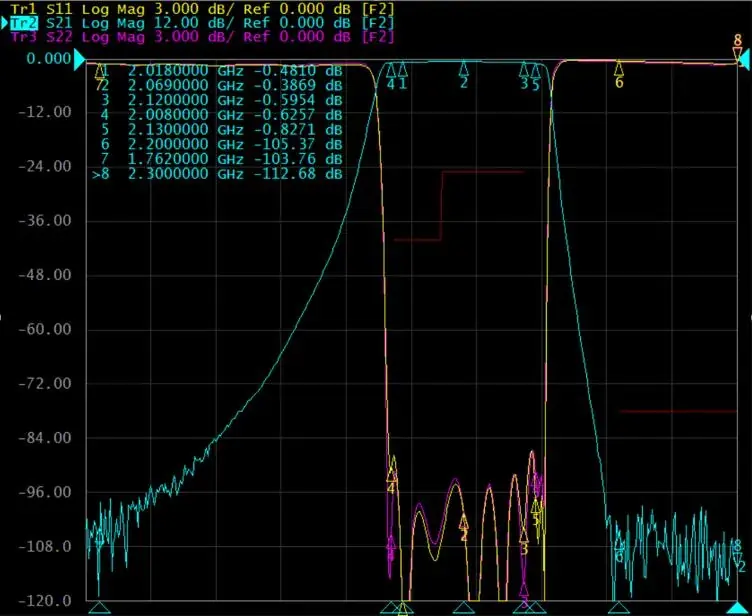
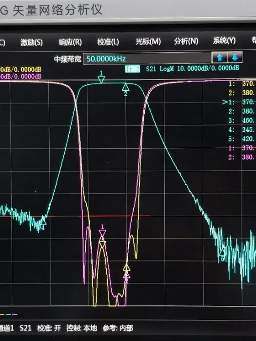
| Bands delivered | 370–380 MHz; 2.018–2.12 GHz; 690–862 / 880–960 MHz |
| Power handling | Average >10 W, peak >100 W; 50 W class cavity filters in production |
| Insertion loss | ≤0.4 dB (outdoor combiner) to <1.5 dB (wide stopband 50 W cavity filter) |
| Out-of-band rejection | >53 dB @0–345 MHz; ≥125 dB @2200–2300 MHz |
| Intermodulation | <-117 dBc (3rd order, 2×43 dBm); up to ≥173 dBc where required |
| Operating temperature | -45 °C ~ +90 °C |
| Surface finish | Selective plating / powder coating / four-face painting (colour to project) |
The module integrates the duplexer, power amplifier and low-noise amplifier into one housing and is delivered as the transmit / receive front-end of a radar system. For the customer this removes the need to manage matching and isolation between filter, PA and LNA at system level. The cost is that thermal design, amplitude and phase tracking, and structural strength inside the module have to be right the first time — they cannot be corrected later with external components.
Miniaturized filters are normally embedded inside the module to provide out-of-band rejection within a limited cavity volume. This is where cavity miniaturization is really tested: when size, power and rejection tighten simultaneously, whether the part can be built determines whether the module exists at all.
| Integrated content | Duplexer + power amplifier + low-noise amplifier |
| Application | Radar transmit / receive front-end |
| Embedded devices | Miniaturized filters (cavity miniaturization) |
| Key acceptance items | TX/RX isolation · amplitude and phase tracking · group delay stability · power handling · thermal design |
| Reference programme | 2069 MHz satcom phased array transmit filter (see Projects) |
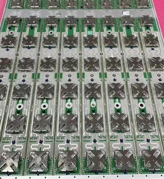
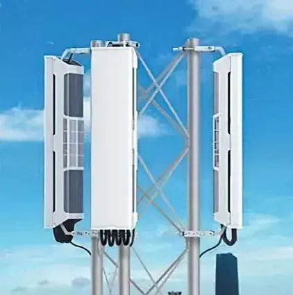
This line covers satellite communication phased array antennas, airborne and vehicle antennas, navigation antennas, and the phase shifters that steer a phased array beam. The way a phased array works sets how demanding the components are: the aperture consists of a large number of identical radiating elements, each generating RF independently, with the total beam formed by their signals combining in space.
Amplitude and phase across elements must therefore track closely. Once tracking is lost, the combined beam points away from its designed direction, sidelobes rise and gain falls. In this line, phase tracking and element-to-element isolation matter more than the extreme limit of a single unit.
| Antenna types | Satcom phased array; airborne and vehicle; navigation |
| Phase shifters | Beam steering for phased array radar |
| Array principle | Many elements combined, signals summed in space to form the beam |
| Key acceptance items | Phase tracking · amplitude tracking · element isolation · beam pointing accuracy |
| Batch consistency | Delivered programmes achieve ±1° batch phase tracking, ±1.6° over the full temperature range |
No topology is better than another; they trade differently. Selection starts by stating the constraints: how much volume is available, how much power must be handled, how much out-of-band rejection is needed, and how much group-delay distortion is allowed.
| Topology | Relative size | Insertion loss | Power handling | Typically suited to |
| Lumped element | Smallest | Low | Low | Low-frequency narrowband, volume-critical |
| Metal cavity | Medium to large | Low | High | High power with high rejection |
| Dielectric-loaded | Small | Medium | Medium | Constrained volume, moderate power |
| Tubular | Small | Medium | Medium | Narrowband, cost-sensitive |
| Air stripline | Medium | Low | Medium to high | Wideband, low loss required |
| Waveguide | Large | Very low | Very high | High frequency, very high power |
Once the topology is fixed, miniaturization advances on three fronts at once: how the resonator is shaped, how the surfaces are finished, and how the structure is kept stable.
Resonator geometry. A proprietary resonator design compresses the volume each cavity requires while raising peak power handling. A smaller cavity concentrates the electric field, so shape changes are validated together with power capability instead of against the dimension alone.
Surface treatment and Q. Resonators and cavity walls are silver plated to reduce conductor loss, and the plating method is chosen deliberately — coating density and thickness uniformity determine the achieved Q. The same structure plated differently gives a measurable difference in insertion loss.
Structure and reliability. A miniaturized cavity has thinner walls and lower stiffness, which a stabilising structural design has to restore so that reliability under shock and vibration does not degrade. This step determines whether the part can actually be installed and used.
A phased array radar replaces mechanical rotation with electronic scanning, so beam switching speed and accuracy are set by the electrical performance of the array. The aperture consists of a large number of identical elements, each independently adjusted in phase and amplitude by the beam controller and phase shifters, producing a predictable radiation pattern and beam direction.
On transmit, the transmitter distributes power through the feed network to each element, and the elements combine that power in space. Power is therefore not concentrated in one chain but distributed across tens to thousands of parallel chains — any tracking deviation in one chain enters the beam directly.
For components in this position, the acceptance emphasis differs from conventional RF parts. The extreme limit of a single unit is not the first concern: batch-to-batch tracking, stability over the full temperature range and repeatability over long-term operation determine whether the system works.
These three requirements conflict directly with making filters and modules smaller with higher power handling: tracking, stability and isolation all rely on structural margin and process controllability — and margin is exactly what miniaturization removes.