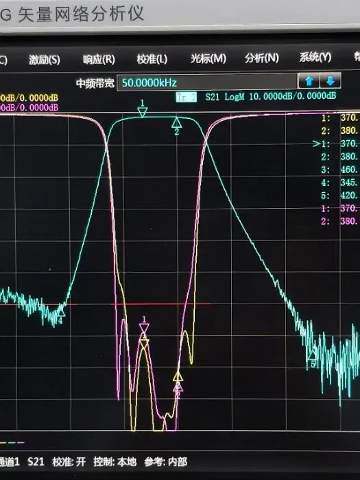
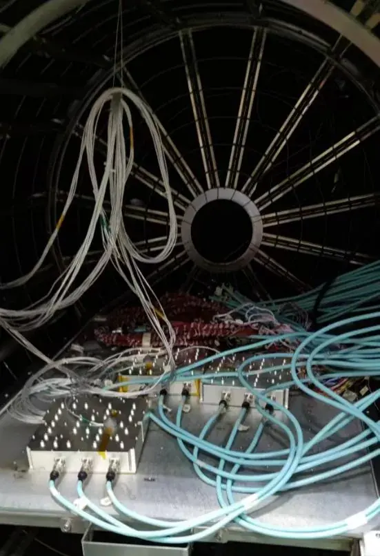
All three programmes below have completed series delivery. The figures are delivered specifications rather than marketing claims, and can be used directly for design comparison.
The satcom phased array transmit filter achieves ≥125 dB out-of-band rejection and ≥173 dBc third-order intermodulation suppression at 23 dBm per tone, while holding batch phase tracking to ±1° and ±1.6° over the full temperature range — the precondition for a phased array aperture to combine its beam stably.
The UAV duplexer operates from -40 °C to +90 °C at 5000 m altitude with the complete unit kept below 1.2 kg and four faces finished in matte GY05 brown-green. The outdoor combiner has built-in surge protection on every port, IP67 or better weather protection, and supports pole or wall mounting.
Each programme is set out as requirement, engineering difficulty, verification method and delivered specification. Specification tables are expanded by default so the figures can be compared directly.
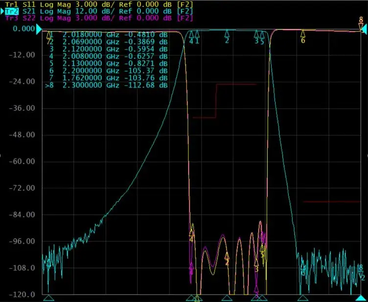
Requirement: Used in the transmit channel of a satcom phased array radar. Transmit and receive share the aperture, and transmit energy is far higher than the received signal, so the filter must suppress transmit-side spurious emissions while keeping the receive channel from being swamped.
Engineering difficulty: Four specifications had to hold at once — receiver noise floor better than -173 dBc, intermodulation of -153 dBm under two-tone 2×23 dBm, TX/RX isolation of -128 dBc, and batch phase tracking of ±1° (±1.6° over temperature). High rejection and high phase tracking conflict by nature: rejection is obtained by adding sections, and more sections make the group delay at the band edge harder to keep flat, while 24-hour delay drift still had to stay within 0.3 ns.
Verification: Intermodulation suppression measured with 23 dBm per tone at the output. Group delay characterised as four separate items — linear distortion, parabolic distortion, in-band ripple and 24 h delay drift. Amplitude and phase tracking sampled across batches and re-measured over -45 °C to +80 °C.
| Centre frequency | f₀ = 2069 MHz |
| Passband | 2.018 GHz ~ 2.12 GHz |
| In-band ripple | ≤0.5 dB @2.018~2.12 GHz |
| Insertion loss | ≤0.8 dB @2.018~2.12 GHz |
| Out-of-band rejection | ≥125 dB @2200~2300 MHz; ≥105 dB @300~1762 MHz |
| Intermodulation | ≥173 dBc measured at 23 dBm per tone at output |
| VSWR | ≤1.2 @2.018~2.12 GHz |
| Amplitude / phase tracking | Amplitude ±0.2 dB, phase ≤±1.6° |
| Group delay | Linear distortion ≤0.08 ns/MHz; parabolic distortion ≤0.01 ns/MHz; ripple ≤1 ns; 24 h drift ≤0.3 ns |
| Operating temperature | -45 °C ~ +80 °C |
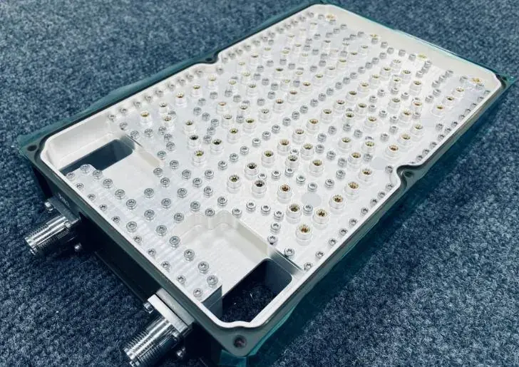
Requirement: An airborne platform where transmit and receive share one antenna, so a duplexer separates the two bands. The airborne environment is much more restrictive than a ground installation: weight feeds directly into payload and endurance, and altitude changes both cooling conditions and electrical clearance.
Engineering difficulty: Power requirements were not relaxed — more than 10 W average and 100 W peak — while insertion loss still had to stay below 1.0 dB with return loss better than -20 dB. The real challenge was environmental: operating temperature spans -40 °C to +90 °C, and delay variation with temperature had to remain under 110 ns, otherwise timing between channels drifts. The complete unit also had to stay below 1.2 kg, so both structure and shielding were calculated closely.
Verification: Insertion loss and return loss by vector network analyser. Power handling tested separately for average and peak. Delay variation captured point by point through a -40 °C to +90 °C temperature cycle. Weight, altitude suitability and surface finish checked item by item against acceptance conditions.
| TX / RX | 758-803 MHz / 703-748 MHz |
| Insertion loss | <1.0 dB |
| Return loss | <-20 dB |
| Power handling | Average >10 W, peak >100 W |
| Delay variation vs temp | <110 ns |
| Operating temperature | -40 °C ~ +90 °C |
| Altitude | 5000 m |
| Weight | Less than 1.2 kg |
| Surface finish | Four faces painted, matte GY05 brown-green |
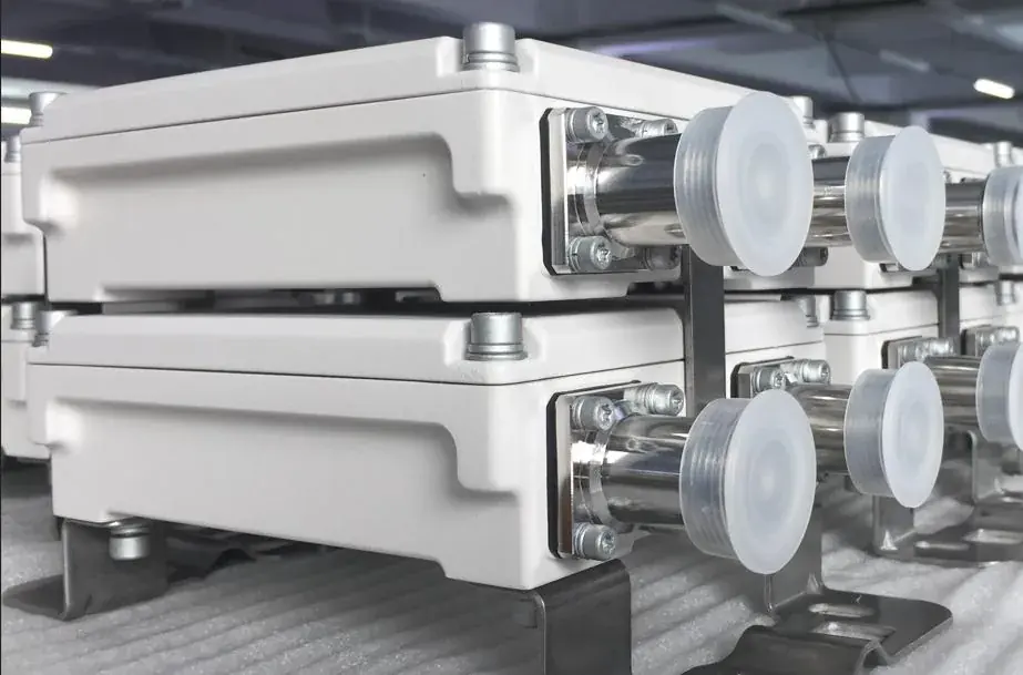
Requirement: A combining unit installed at the antenna outdoors, combining two bands onto a single feed. The equipment is permanently exposed with long service intervals, so reliability had to be designed in from the start — it is too late to recover it through maintenance.
Engineering difficulty: Every port required built-in surge protection alongside IP67 or better weather protection. Electrically the two bands must not interfere: isolation ≥50 dB, VSWR ≤1.2, and insertion loss down at 0.4 dB. The harder problem was intermodulation at high power — third-order products had to be held at the -120 dBm level under two-tone 2×43 dBm excitation, which places hard constraints on cavity contact surfaces, plating and assembly process.
Verification: Third-order PIM measured under two-tone 2×43 dBm. Isolation and VSWR measured point by point in each band. Insertion loss confirmed separately across 690-862 MHz and 880-960 MHz. Surge protection and IP67 rating verified under type-test conditions, and the powder coating inspected for appearance and adhesion.
| Frequency bands | 690-862 / 880-960 MHz |
| Insertion loss | ≤0.4 dB |
| Isolation | ≥50 dB @690-862 / 880-960 MHz |
| VSWR | ≤1.2 @690-862 / 880-960 MHz |
| PIM | <-117 dBc (3rd order, 2×43 dBm) |
| Operating temperature | -45 °C ~ +80 °C |
| Surface finish | Powder coated |
Every line in the tables above corresponds to a test method. A specification table is only meaningful if the measurement basis is stated — the same device measured differently can give a completely different conclusion.
S-parameter items. Insertion loss, return loss, VSWR, passband width and in-band ripple are swept point by point with a vector network analyser over the specified band, with test temperature and calibration state recorded. Insertion loss depends on calibration accuracy, so the instrument is recalibrated before every measurement.
Intermodulation items. Passive intermodulation is measured under two-tone excitation, with the two carriers applied at the agreed power (2×23 dBm and 2×43 dBm in the programmes above) and the third-order product level read out. PIM is extremely sensitive to contact-interface condition, so this test doubles as an assembly-quality check.
Group delay and amplitude / phase tracking. Group delay requires separate readings of linear distortion, parabolic distortion and in-band ripple, plus a long observation to confirm drift; amplitude and phase tracking requires cross-batch sampling and re-measurement over the full temperature range in a thermal chamber — one unit passing does not mean every batch passes.
Environment and reliability. Temperature cycling, burn-in and power loading are carried out in thermal and burn-in chambers to expose material and structural weaknesses. Outdoor products additionally require separate verification of surge protection and ingress protection.