We design and manufacture high-performance passive and active RF components — cavity filters, duplexers and combiners, radar transceiver modules, phase shifters and antennas — engineered to the specific constraints of each application rather than to a catalogue.

 Subsidiary of Shenzhen Gaogeqi Technology
GCT is a subsidiary of Shenzhen Gaogeqi Technology Co., Ltd. and a National High-Tech Enterprise specialising in the design and manufacture of RF components and antenna feed sub-systems.
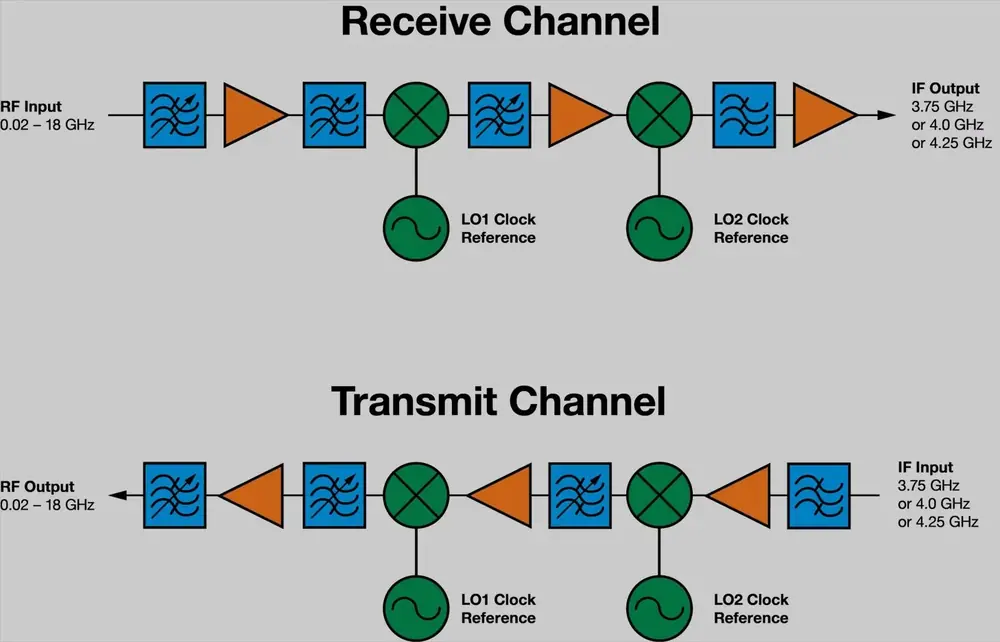
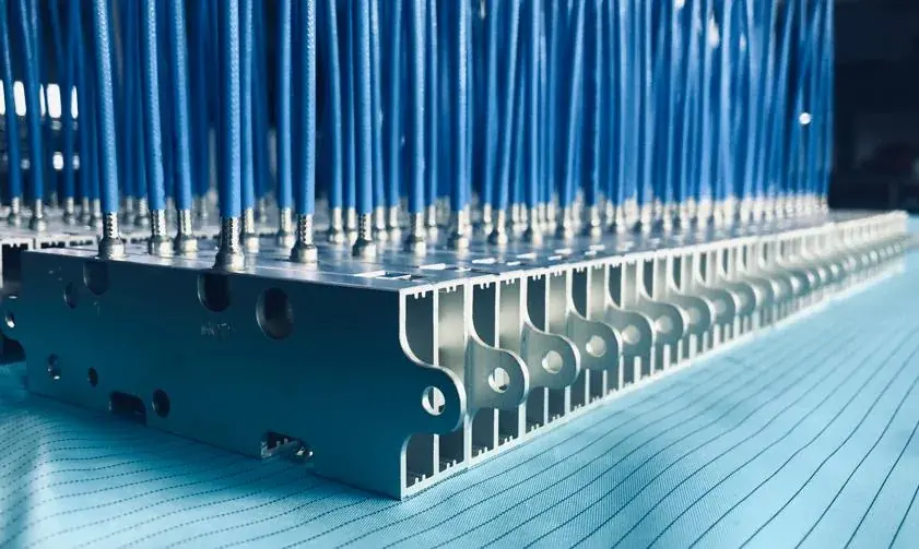
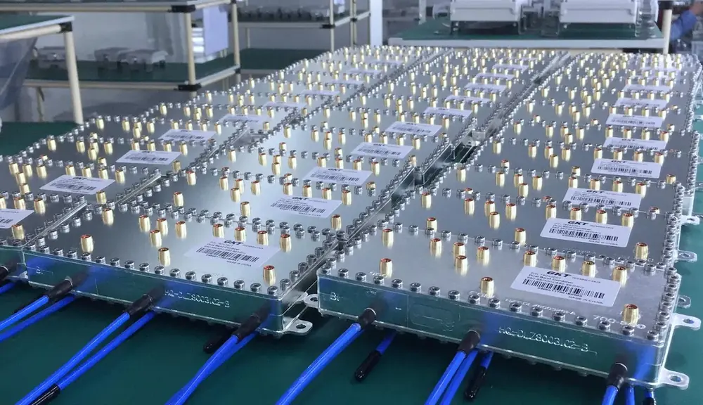
Our product range covers passive filters, transceiver modules, phase shifters and antennas for phased array radar, UAV platforms, satellite communication and base station applications.
Every project starts from the operating scenario. We develop and manufacture to the customer's constraints — available envelope, power level, rejection requirement, thermal and mechanical environment — and deliver the solution that fits, rather than the closest item in a catalogue.
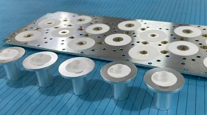
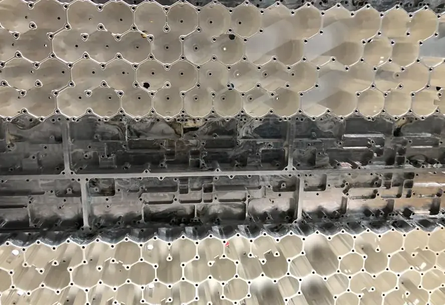
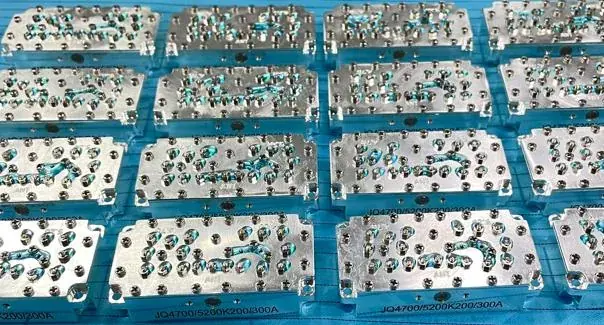
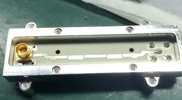
Passive filters, integrated transceiver modules, and antennas with phase shifters — covering antenna feed systems, antenna-embedded components and radar front-ends.
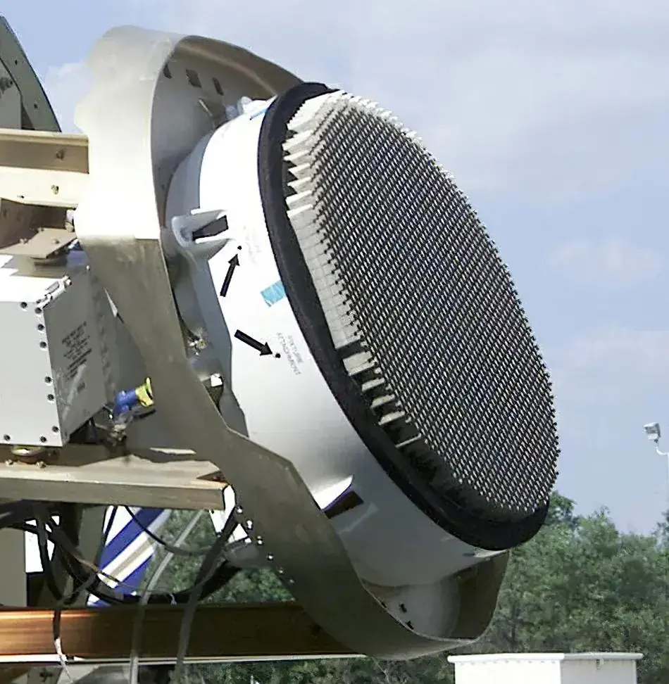
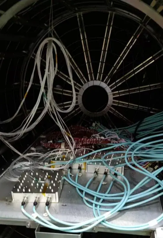
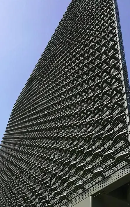
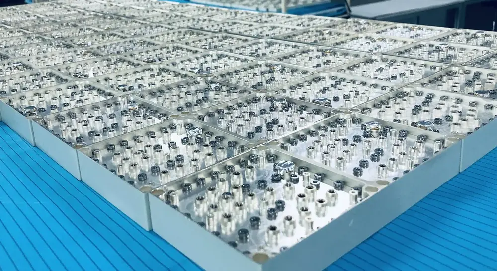
In a phased array radar the beam is steered electronically, so beam switching speed and accuracy are set by the electrical performance of the array itself. The aperture is built from a large number of identical radiating elements, each of whose phase and amplitude is independently controlled by the beam controller and phase shifters.
On transmit, the transmitter distributes power through the feed network to every element, and the power is combined in space. Power is therefore spread across tens to thousands of parallel chains rather than concentrated in one — and a deviation in any single chain goes straight into the beam.
For components in this position, the acceptance criteria differ from those of ordinary RF parts. Absolute single-unit limits matter less than unit-to-unit consistency, stability over the full temperature range, and repeatability over long-term operation.
These three requirements pull directly against miniaturization and power handling: consistency, stability and isolation all depend on structural margin and process control — and margin is exactly what shrinking the package consumes.
Three production programmes, with the delivered specification shown as measured rather than as an advertising claim.
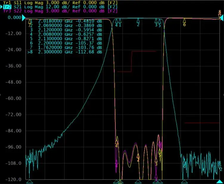
Requirement: Four specifications had to hold simultaneously — receiver noise floor better than -173 dBc, PIM of -153 dBm under two-tone 2×23 dBm, TX/RX isolation of -128 dBc, and batch phase consistency of ±1° (±1.6° across the full temperature range). High rejection and high phase consistency pull against each other: rejection is obtained by adding sections, and each added section makes the group delay at the band edge harder to keep flat.
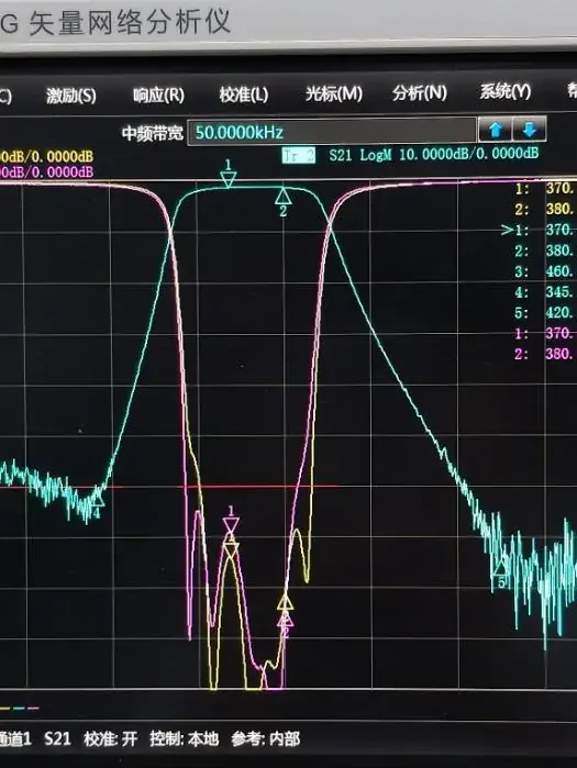
How it was verified: Intermodulation was measured at 23 dBm per tone at the output. Group delay was characterised separately as linear distortion, parabolic distortion, in-band ripple and 24-hour delay drift. Amplitude and phase tracking was sampled across batches and re-measured over -45 °C to +80 °C.
| Centre frequency | f₀ = 2069 MHz |
| Passband | 2.018 GHz ~ 2.12 GHz |
| In-band ripple | ≤0.5 dB @2.018~2.12 GHz |
| Insertion loss | ≤0.8 dB @2.018~2.12 GHz |
| Out-of-band rejection | ≥125 dB @2200~2300 MHz; ≥105 dB @300~1762 MHz |
| Intermodulation | ≥173 dBc measured at 23 dBm per tone at output |
| VSWR | ≤1.2 @2.018~2.12 GHz |
| Amplitude / phase tracking | Amplitude ±0.2 dB, phase ≤±1.6° |
| Group delay | Linear distortion ≤0.08 ns/MHz; parabolic distortion ≤0.01 ns/MHz; ripple ≤1 ns; 24 h drift ≤0.3 ns |
| Operating temperature | -45 °C ~ +80 °C |
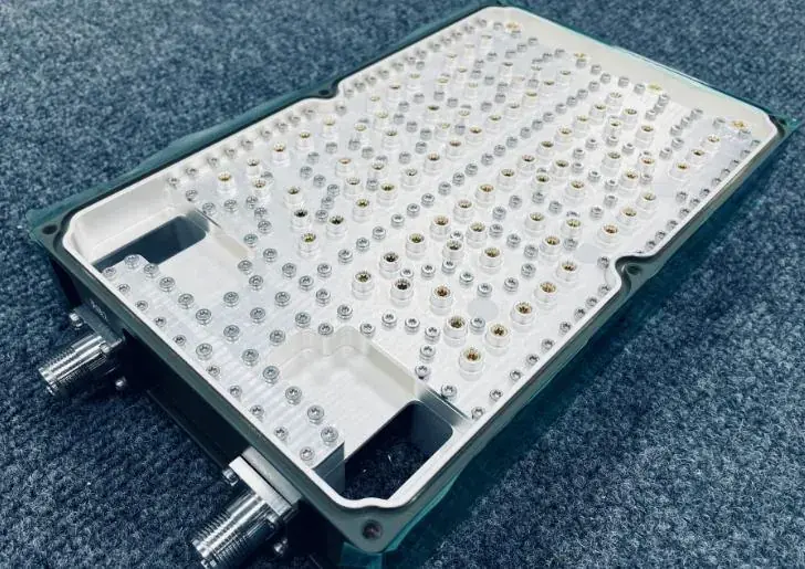
Requirement: TX and RX share one antenna on an airborne platform, so the duplexer has to separate the two bands. The airborne environment is far more restrictive than a ground installation: weight feeds directly into payload and endurance, and altitude changes both cooling conditions and electrical clearances. Insertion loss had to stay below 1.0 dB with return loss better than -20 dB while handling more than 10 W average and 100 W peak.
How it was verified: Insertion loss and return loss by vector network analyser; power handling by separate average and peak loading; delay variation sampled point by point through a -40 °C to +90 °C temperature cycle; weight, altitude suitability and surface finish checked against acceptance conditions.
| TX / RX | 758-803 MHz / 703-748 MHz |
| Insertion loss | <1.0 dB |
| Return loss | <-20 dB |
| Power handling | Average >10 W, peak >100 W |
| Delay variation vs temp | <110 ns |
| Operating temperature | -40 °C ~ +90 °C |
| Altitude | 5000 m |
| Weight | Less than 1.2 kg |
| Surface finish | Four faces painted, matte GY05 brown-green |
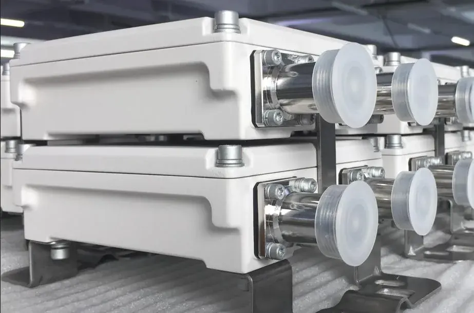
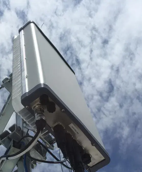
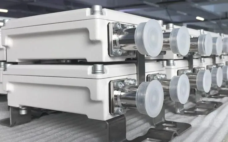
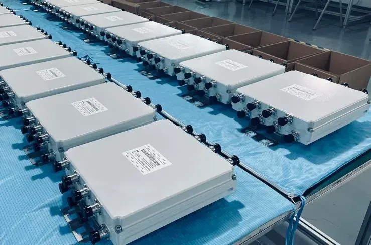
Requirement: A combiner mounted at the antenna that combines two bands onto one feed. The unit is permanently exposed outdoors with long service intervals, so reliability had to be designed in from the start rather than recovered through maintenance. Every port carries built-in surge protection and the enclosure is rated IP67 or better.
How it was verified: Third-order PIM measured under two-tone 2×43 dBm excitation; isolation and VSWR measured point by point in each band; insertion loss confirmed separately across 690-862 MHz and 880-960 MHz; surge protection and IP67 rating verified under type-test conditions; powder coating inspected for appearance and adhesion.
| Frequency bands | 690-862 / 880-960 MHz |
| Insertion loss | ≤0.4 dB |
| Isolation | ≥50 dB @690-862 / 880-960 MHz |
| VSWR | ≤1.2 @690-862 / 880-960 MHz |
| PIM | <-117 dBc (3rd order, 2×43 dBm) |
| Operating temperature | -45 °C ~ +80 °C |
| Surface finish | Powder coated |
RF component development crosses several disciplines at once: electromagnetic field distribution, structural design, material selection, chemical surface treatment and production process.
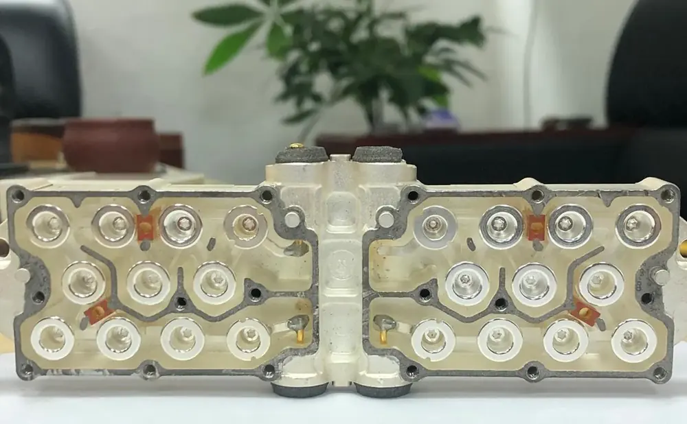
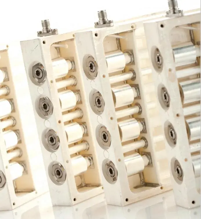
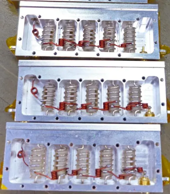
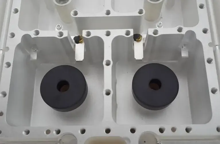
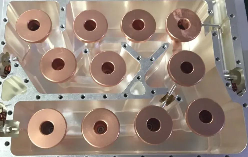
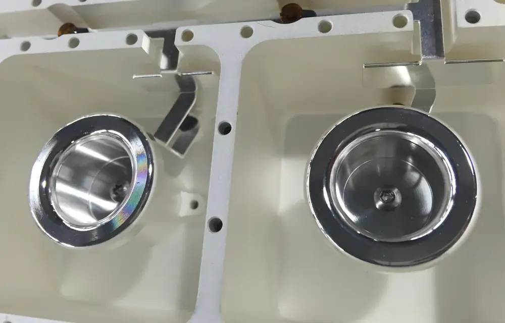
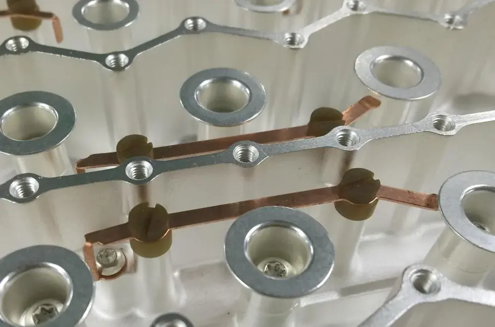
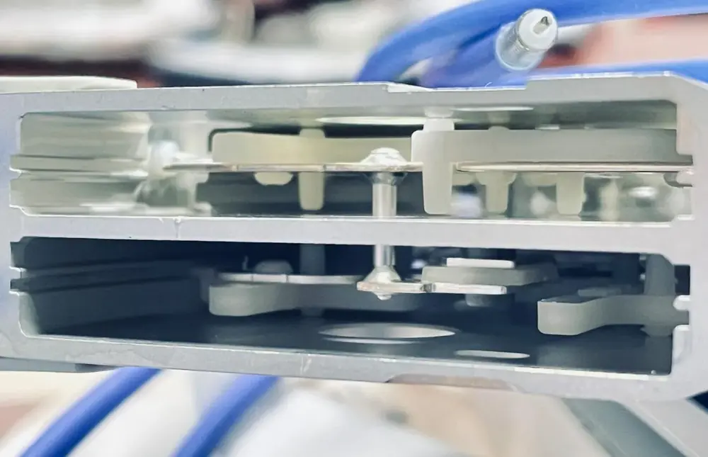
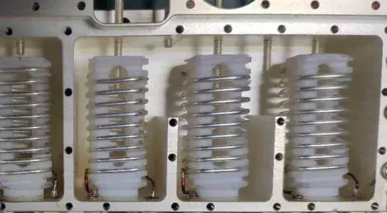
Resonator geometry. A proprietary resonator design reduces the volume each cavity needs while raising peak power handling. Shrinking a cavity concentrates the electric field, so geometry changes are validated together with power capability rather than against dimensions alone.
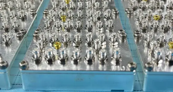
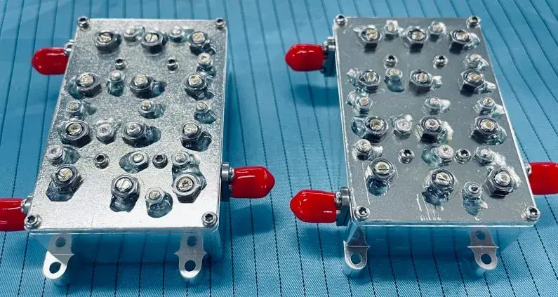
Plating and Q. Resonators and cavity walls are silver plated to cut conductor loss, and the plating process is selected deliberately — coating density and thickness uniformity determine the achieved Q, and the same structure plated differently shows a measurable difference in insertion loss.
Structure and reliability. A miniaturized cavity has thinner walls and less stiffness, so a stabilizing structure is designed in to keep reliability under shock and vibration unchanged. This step decides whether the part can actually be deployed.
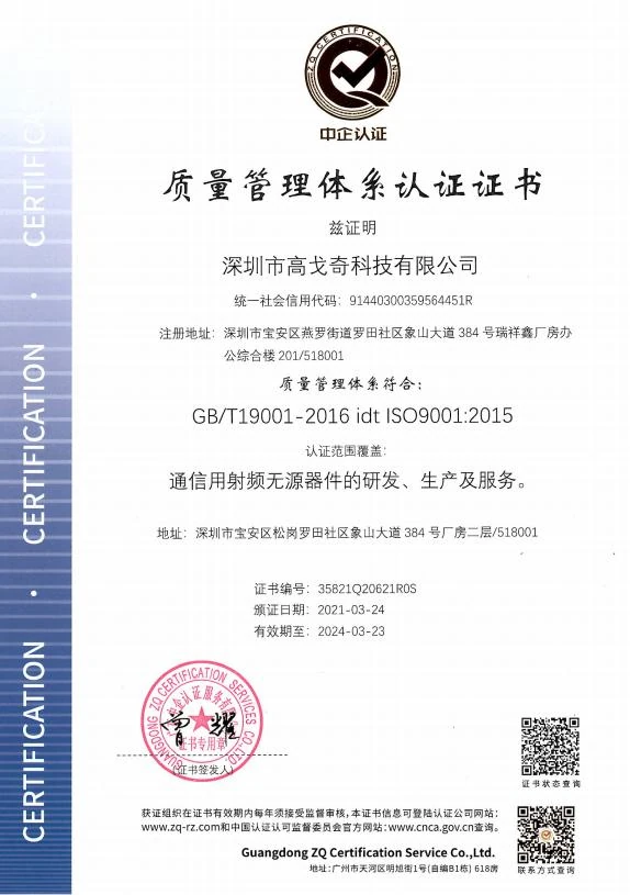
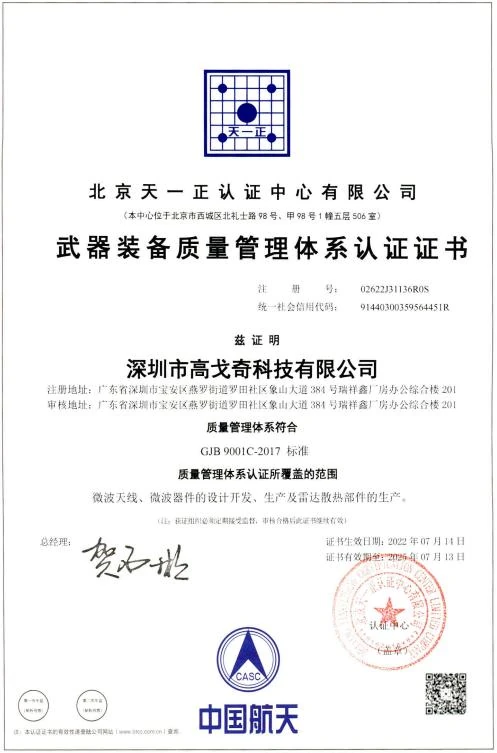
Our quality system satisfies two standards at once: ISO 9001 and the Chinese military equipment quality management standard GJB 9001C-2017. The scope covers development, production and service of RF passive components for communication equipment.
Vector network analysers · signal generators · spectrum analysers · PIM test sets · high-frequency induction welding · automated welding · automated screwdriving · thermal chambers · burn-in chambers, plus dedicated high-power and high-frequency test systems for specialist verification and automated test.
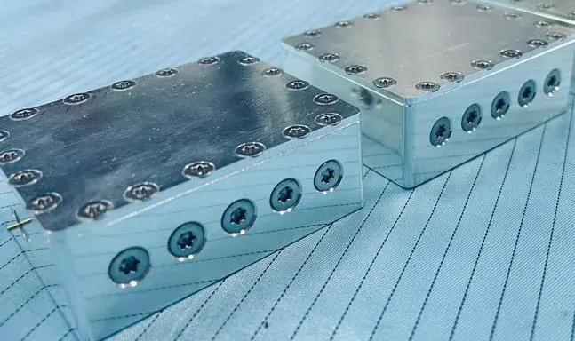
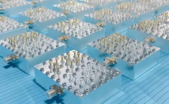
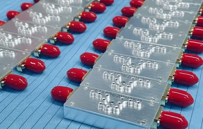
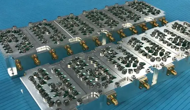
Components and sub-systems delivered to customers across four continents.